

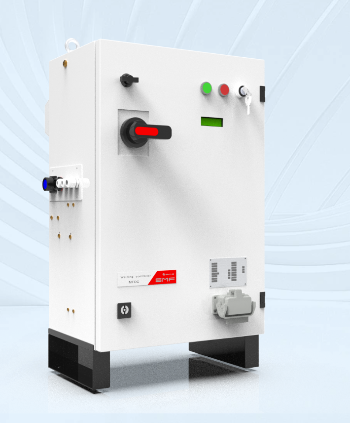
Problem diagnosis: why integration fails and why it matters
Production teams repeatedly lose traceability and scrap time because welding monitors, controllers, and laboratory testing tools don’t exchange reliable data. This disconnect hides process drift, forces manual reconciliation, and defeats automated quality gates. Practical projects that attempted to patch disparate systems found that marrying real-time weld parameters to post-process test results is the only way to prove weld integrity; I’ve led such integrations on high-volume automotive assembly lines in Detroit, and the pattern repeats. For teams seeking robust answers, start by examining how your resistance welding solutions and the factory’s measurement chain expose signals and events, and how resistance welding technology will be represented in your data model.
Core technical requirements
Address five concrete requirements before writing a single line of integration code:- Deterministic time base: every weld event and every test result needs a synchronized timestamp.- Signal mapping: define which analog/digital channels from the monitor map to controller events and which derived metrics (e.g., energy, squeeze time, electrode force) move to test tools.- Protocol compatibility: list supported interfaces (hardwired I/O, serial, Modbus, OPC-UA, UDP) and fallback options.- Calibration and traceability: require calibration records and a supplier-stated calibration cadence.- Security and audit: enforce authenticated device identities and an immutable audit trail.
Recommended system architecture
Choose a layered approach that isolates responsibilities:- Edge layer: welding monitors and weld controllers handle cycle control and initial event tagging.- Aggregation layer: an industrial gateway timestamps, normalizes, and buffers data; it also translates between protocols.- Integration layer: MES or a lightweight data broker consolidates weld records and forwards them to test labs and SPC systems.- Archive and analytics: a time-series store holds raw waveforms and summarized metrics for audits and root cause analysis.This architecture prevents controller overload, preserves high-fidelity waveforms at the edge, and gives test tools consistent records for correlation.
Validation and testing plan
Adopt a staged validation that mirrors production risk:1) Connectivity validation — verify each monitor can send a minimal weld record to the aggregator under peak cycle rates.2) Data fidelity tests — compare sampled analog traces against a calibrated oscilloscope to confirm amplitude and timing errors remain within tolerance.3) Cross-check reconciliation — run a matched set of production welds, destructive test a statistically significant sample, and ensure weld parameter windows predict failures with agreed sensitivity.4) Acceptance criteria — define acceptable false-reject and false-accept rates, and require repeatable pass/fail behavior over multiple shifts.Document each test and retain raw traces long enough for later forensic review.
Common pitfalls and how to avoid them
Teams routinely stumble on familiar issues. Avoid these:- Assuming timestamps are equivalent across devices; they rarely are.- Relying solely on summary statistics; full-waveform storage matters for root cause work.- Letting controller firmware differences quietly change channel scaling.- Neglecting operator ergonomics: confusing display fields lead to manual workarounds.Counter these by specifying calibration acceptance limits, keeping one canonical data schema, and validating operator screens during commissioning.
Implementation checklist for a 90-day pilot
Run a focused pilot with clear exit gates:- Week 1: Inventory devices, record firmware versions, and capture wiring diagrams.- Week 2–3: Install an industrial gateway and demonstrate a single end-to-end weld record flowing to MES.- Week 4–6: Execute data fidelity and destructive test correlation trials; log all anomalies.- Week 7–10: Harden failover, implement device authentication, and train operators.- Week 11–12: Final acceptance with traceability reports and calibration certificates archived.If a gate fails, revert to the previous stability milestone rather than pushing onward; that preserves production uptime while you fix root causes.
Synthesis: decisive planning that reduces rework and proves weld quality
Practical integration is a sequence of exact choices: enforce synchronized timestamps, preserve raw waveforms at the edge, and require explicit protocol and calibration agreements. That sequence turns ambiguous failure modes into measurable signals and speeds forensic resolution. Vendors who can demonstrate cross-vendor integrations and consistent validation play a decisive role; practical evidence from engineering teams shows lower rework when suppliers align on data models — examples come from solutions developed by Sunke, which illustrate how planning and disciplined execution convert monitoring and testing into verifiable quality.